Description
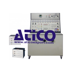
The Thyristor and Diode Trainer is a versatile teaching aid. It explores the principles and applications of thyristors, diodes and converters. The control panel has clear mimic diagrams with shrouded sockets. Students use shrouded leads (included) to connect the diff erent parts of the circuits. The parts include thyristors, diodes, inductors, transformers and smoothing capacitors. A mix of standard analogue meters and a multifunction digital meter measure the currents and voltages in the circuits. The multi-tapped transformers give a choice of single and three-phase AC voltages for connection to the diodes and thyristors. A centre-tapped interphase transformer shows the eff ect of reducing circulating currents in rectifi er circuits. A load inductor shows the eff ect of inductance when smoothing the AC ripple in rectifi er circuits. Fast-blow fuses on the control panel protect the load side of experiment circuits. Students use controls on the lower panel to adjust AC supply voltage and ballast resistance during experiments. For thyristor experiments, students can select an external or internal source to trigger the gates of the thyristors. A variable control delays the gate fi ring pulse for clear demonstrations of the eff ect of fi ring delay on harmonics and output waveforms. Transducers allow students to connect an oscilloscope (included) to show and compare the gate pulses with the output waveforms. We supply this product with three loadbanks: two resistive and one inductive. It also includes a two-channel oscilloscope (OS2).
Learning Outcomes
- Single-phase and polyphase diode rectifi er circuits
- Single and three-phase fully controlled thyristor bridge circuits
- Single-phase AC control using thyristors
- Rectifi er harmonics, output smoothing methods and inverted operation
- Commutation eff ects in polyphase and single-phase rectifiers
Features
- Fully equipped for both single and threephase experiments
- Internal or external thyristor fi ring control source
- Selectable gate pulse monitor connection to compare fi ring pulse with output waveforms
- Variable thyristor firing delay for studies of harmonics and eff ect of fi ing delay on output waveforms
- Transducers and oscilloscope included for waveform monitoring
- Supplied with resistive and inductive loads
- Includes multi-tapped transformers to investigate diff erent power supply characteristics
Specifications
ATICO is committed to a programme of continuous improvement; hence we reserve the right to alter the design and product specification without prior notice.
NETT DIMENSION AND WEIGHT: 1750 mm high x 1320 mm wide x 870 mm front to back and 431 kg
Approximate packed volume and weight: 4.8 m3 and 650 kg
Load banks: Refer to separate datasheets
Oscilloscope: Two channel
Transformers (three off):
1 kVA single phase – primary tapped at 220 V and 380 V.
Two secondary windings, both at 52 V. One secondary winding tapped at 8 V. Each secondary winding protected by an ultra-fast-blow fuse.
Semiconductors:
• 6 x power diodes
• 6 x power thyristors
Other wound components:
• 10 mH inductor, tapped at 5 mH
• 52 mH interphase transformer, centre-tapped
Transducers:
• 2 x voltage transducers 40 V in = 1 V out
• 3 x current transducers 2 A in = 1 V out
Operating Conditions
- Operating Environment:
Laboratory - Storage Temprature Range :
–25°C to +55°C (when packed for transport) - Operating Temprature range:
+5°C to +40°C - Operating relative humidity range:
80% at temperatures < 31°C decreasing linearly to 50% at 40°C

