Description
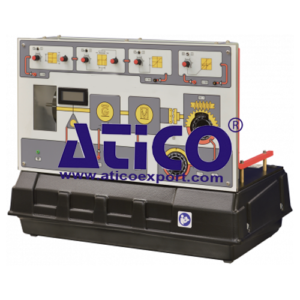
The Servo Trainer shows DC servo position and speed control systems using typical industrial techniques. It has a DC servomotor, a DC generator and a flywheel mounted on a common shaft. Analogue 0 to ±10 V control signals vary the servomotor shaft speed in either direction. An optical sensor measures the speed and shows it on a panel-mounted digital meter. The DC generator statically or dynamically loads the servomotor. An electric clutch connects or disconnects the shaft to a 30:1 reduction gearbox for position control studies. A manual control allows the user to set a position control setpoint. To adjust the shaft inertia, the comes with two extra interchangeable inertia discs (flywheels). For advanced experiments, the Servo Trainer includes extra ‘block’-type circuits that can add non-linear and fully adjustable effects of:
• Deadzone or ‘deadband’
• Anti-deadzone
• Hysteresis
• Saturation
These blocks are important in studies of servo systems because they mimic problems that happen in real applications.
Learning Outcomes
- Basic tests and transducer calibration
- Response calculation and measurement
- Proportional and proportional plus integral control of servo-system speed
- Disturbance cancelling and feedforward control
- Angular position control: proportional control and velocity feedback
- Angular position control and the influence of nonlinearities
- Non-linear system characteristics
- The flexible design of the equipment allows the user to develop many other analysis and control exercises to suit their needs. It is good for extended or advanced control experiments, and is ideal for student project work.
Specifications
ATICO is committed to a programme of continuous improvement; hence we reserve the right to alter the design and product specification without prior notice.
Nett dimensions and weight:
540 mm x 330 mm x 420 mm; 18.7 kg
Packed dimensions and weight:
0.3 m3, 41 kg (approx – packed for export)
Inputs (0–10 VDC):
Motor control signal: 0 to +/– 10 VDC
Generator load control
Signal conditioning blocks – deadzone, anti-deadzone and saturation: 0 to +/– 10 VDC
Hysteresis block: 0 to +/– 10 VDC
Outputs (0–10 VDC):
Reference Set Point – 0 to +/– 10 VDC
Servomotor shaft speed
Gearbox position (angle)
Signal conditioning blocks – deadzone, anti-deadzone and saturation: 0 to +/– 10 VDC
Hysteresis block
Other connections: 0 to 10 VDC
User-adjustable position (angle) setpoint
Other parts included:
Connecting cables
Operating Conditions
- Operating Environment:
Laboratory - Storage Temprature Range :
–25°C to +55°C (when packed for transport) - Operating Temprature range:
+5°C to +40°C - Operating relative humidity range:
80% at temperatures < 31°C decreasing linearly to 50% at 40°C

