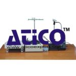
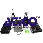
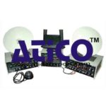
Features of Satellite Trainer:
• Emulation of path loss at uplink and downlink
• Emulation of frequency translation
• High RF output power and low noise
• PLL synthesizer in Transmitter, Receiver and Satellite
• Condenser microphone and speaker for audio link
• Camera and Monitor for video link
• 4 Dish for linear polarization study
• C/N and S/N measurement facility
• Transmit Audio, Video, Digital/Analog data, Tone, Voice, function generator waveforms etc =.
• Receives & demodulates 3 Signals Simultaneously Satellite Trainer
Technical Specifications
Satellite Uplinking Transmitter
Frequency : 4 channels in 5.8 Ghz band ; PLL with frequency selection switch & LED indication
RF output level : +3 dBm nominal with wideband RF amplifier with no manual matching required
Audio 1 : Int. 1KHz sine wave / Ext Mic Ext. Function Generator waveform
Audio 2 : Int. 1KHz sine wave / Ext Mic Ext. Function Generator waveform
Video : Analog Camera/VCD compatible
Waveform : upto 5MHz Function Generator
Digital : Max rate 100KHz typical
Baseband : Transmits 3 signals simultaneously at each uplink frequency
Processor : PIC16F4 – 8 bit RISC processor based PLL with 4 Mhz clock
Bandwidth : 16 Mhz
Modulation : 5/ 5.5MHz Audio FM Modulation 8 Mhz Video FM Modulation
Antenna : Detachable Parabolic dish with mount
Inputs : separate terminals for different inputs
Power Supply : 100-240VAC 47-63Hz
Satellite Trainer Downlink Receiver
Frequency : 4 channels in 5.8 Ghz band PLL Controlled ISM Band
Sensitivity : -80dBm
Audio 1out : Speaker inbuilt/output
Audio 2 out : Speaker inbuilt/output
Video Out : 5MHz, 1V p/p
Digital : Max rate 100KHz typical TTL RSSI Out : Received signal strength output for C/N measurement
Antenna : Detachable Parabolic dish with mount
Demodulation : Receives & demodulates 3 signals simulataneously
Power Supply : 100-240VAC 47-63Hz
Satellite Link Emulator
Transponder Uplink
Frequency : 4 channels in 5.8 GHz band ; PLL Synthesized ISM Band with select switch
Sensitivity : -80dBm Transponder Downlink
Frequency : 4 channels in 5.8 Ghz band; PLL Synthesized ISM Band
RF output level : 0 dBm nominal
Path Loss : Variable attenuation
Band limiting : 16MHz fixed typical
Antennas : Detachable Parabolic Dish
Power Supply : 100-240VAC 47-63Hz
Area and Scope of Experimentation:
* To set up a passive satellite communication link and study their difference. To study the communication satellite link design: process of transmitting a signal to a satellite (UPLINKING), reception of same signal via satellite (DOWN LINKING) and functioning of transponder of a satellite
* To measure the baseband analog signal parameters in a satellite link
* To measure the signal parameters in an analog FM/FDMTV Satellite link
* To study the functionality of a satellite MODEM
* To study the phenomenon of Linear polarization
* To measure the C/N ratio
* To measure the S/N ratio
* To study the effect of fading and measure the fading margin of a received signal
* To measure the digital baseband signal parameters in a satcom link
Accessories:
* Camera
* Monitor
* Cables BNC-BNC 2Nos
* Serial Communication Software


