Description
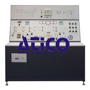
The Salient Pole Generator explores the principles and characteristics of salient pole generators. It contains everything needed for salient pole generator experiments including resistive, capacitive and inductive load banks. The open and flexible design is ideal for lecturers to create their own experiments, as well as student project work. To allow realistic investigations, the characteristics of the prime mover and generator are similar to industrial turbine and generator sets. The prime mover and generator set is two coupled machines mounted on a common bedplate in the base of the console. Manual or automatic voltage regulation (AVR) excitation controls the output voltage of the generator. When the generator is in overrun mode, resistors dissipate the reverse power. A vector drive controls the speed of the prime mover and allows investigations into load flow in positive and negative directions. An integral shaft encoder allows load angle analysis. The user may synchronise the generator output to the grid supply using a synchroscope. They may also use the set of three coloured lamps. The control and protection circuits work when the generator is unsynchronised and synchronised to the mains electrical supply. When the generator is synchronised, the user can operate a variable quadrature droop for reactive power regulation. For protection tests, the protection relay connects to the test circuits through current transformers (CTs) and a voltage transformer (VT). The user connects and sets the protection relay to detect line and earth currents, voltage and frequency faults. The relay also monitors and measures fault events and disturbances for fault analysis. The user sets the relay from its local control panel, or by a cable link to a suitable computer (computer not included) and software (included). When the user applies a circuit fault, the relay opens circuit-breakers in the test circuits. The circuit breakers also include hand-operated switches and lamps. The lamps show whether the circuit-breakers are open or closed. Transducers with BNC connections allow voltage and current waveform measurement, display and analysis using an external oscilloscope (not supplied). For more experiments in protection, the unit has an extra socket to connect an additional protection relay (available separately). Supplied with the equipment is a set of shrouded leads for the user to connect the test circuits together. The unit includes an emergency switch, a mains supply isolator and protection fuses.
Learning Outcomes
- Generator voltage and frequency control
- Voltage, speed and field current characteristics
- Generator open and short circuit tests
- Load tests
- Normal and sudden short-circuit tests
- Zero power factor test
- Synchronising and parallelling
- Control of real and reactive power
- Protection relays
Features
- Includes prime mover and generator to simulate power generation
- Includes transmission line, supplies, circuit protection, internal load banks, instruments and controls
- Synchroscope and synchronising lamps for extended tests
- Built-in industrial-standard digital protection relay gives wide range of functions – module also includes extra socket for additional relay to give even more experiments
- Manual or automatic generator excitation
Specifications
ATICO is committed to a programme of continuous improvement; hence we reserve the right to alter the design and product specification without prior notice.
Nett dimensions and weight:
1850 mm long x 1870 mm high x 960 mm and 750 kg
Packed volume and weight: 5.0 m3 and 1050 kg
Generator: 6.5 kVA maximum (operated at a nominal 2 kVA), 0.8 pf, four-pole, three-phase salient pole a.c. generator. 50 Hz, 1500 rev. min–1 and 60 Hz, 1800 rev. min–1. Automatic voltage regulator (AVR) or manually excited.
Prime mover: 7.5 kW, four-pole, three-phase induction motor. Includes a shaft encoder and cooling fan. Driven by a four-quadrant a.c. vector drive.
Instruments:
Prime mover power and speed
Multi-function meter for a.c. measurements (voltage, current, power factor, power, VAr and VA)
Load angle meter
Generator excitation voltage and current
Synchroscope and three lamps
Incoming running voltage and frequency
Protection Relay:
Generator Protection Relay with under and over frequency protection, and overcurrent and overvoltage protection
Operating Conditions
Operating Environment:
Laboratory
Storage Temprature Range :
–25°C to +55°C (when packed for transport)
Operating Temprature range:
+5°C to +40°C
Operating relative humidity range:
80% at temperatures < 31°C decreasing linearly to 50% at 40°C

