Description
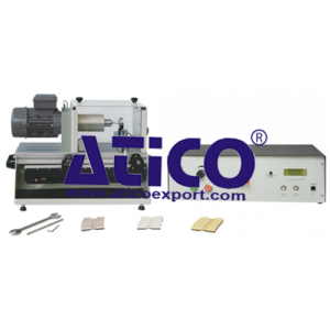
This machine demonstrates the fatigue failure of materials when subject to alternating stresses. Based on Wohler’s design, it uses a motor to rotate a circular cantilever specimen with a load at its free end. It is in two parts: a robust main unit, and a separate control and instrumentation unit. A variable speed drive controls the motor to allow safe and gradual increase of the cycle rate. The motor turns a compliant coupling and a precision shaft held in sturdy bearings. A collet type chuck on the end of the shaft grips the specimen with reliable and accurate concentricity. This reduces set up time and unwanted vibration. The specimens have a special design that creates a point of maximum stress at their midpoint rather than at their end. This gives a defi nite point of failure and avoids unwanted stress concentrations. A gimbal mounted self-aligning bearing holds the ‘free end’ of the specimen. The gimbal assembly links to a short load arm. This applies a purely vertical load even when the specimen defl ects unader load. A load cell links the short load arm to a longer load arm. The longer load arm has an integral moveable dead weight that sets the load. The load cell measures the load and an electronic sensor measures shaft rotation. The separate control and instrumentation unit shows the load, speed (cycle rate) and the number of cycles. A switch cuts power to the drive motor when the specimen fails, stopping the test. This freezes the cycle display at failure to record the result, even without the operator being present. Unlike some designs, the mechanism shuts off the motor only when the specimen actually breaks (not when the specimen is near to failure). A removable clear guard covers the rotating parts. It has an interlock switch to stop the motor if you remove the guard. The machine includes aluminium, steel and brass specimens and tools to fi t and remove them. we can also supply extra specimens to work with this machine. The base of the main unit includes a handy storage area to store the tools and specimens when not in use. The control and instrumentation unit connects to Versatile Data Acquisition System (VDAS®). This gives accurate real-time data capture, monitoring and display, calculation and charting of all important readings on a computer (computer not included). This may allow you to use a networked computer and remotely monitor your tests. This could be especially useful during tests of long duration.
Learning Outcomes
Low and high-cycle fatigue
How to create and use Wohler (S-N) curves for various materials
Comparison of fatigue properties of various materials
Specifications
ATICO is committed to a programme of continuous improvement; hence we reserve the right to alter the design and product specifcation without prior notice.
Dimension and weight:
Main unit: 600 mm x 350 mm x 400 mm high and 30 kg
Control and instrumentation unit: 400 mm x 350 mm x 180mm and 7.5 kg
Total packed dimension :
60 kg and 0.25 m3
Maximum stress :
Approximately 350 MPa
Maximum cycle count:
9.99 x 10⁸ with a one-cycle resolution
Specimens included:
• 20 RF1010 (steel)
• 20 RF1020 (aluminium)
• 20 RF1030 (brass)
Tols includeed :
Spanner, tommy bar, hexagon tool
Operating Conditions
Operating environment:
Laboratory
Storage temperature range:
–25°C to +55°C (when packed for transport)
Operating temperature range:
+5°C to +40°C
Operating relative humidity range:
80% at temperatures < 31°C decreasing linearly to 50% at 40°C

