Specification
Make Complex Changes Of State Of Refrigerating Plants/Heat Pumps Visible And Tangible
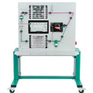
Refrigeration Circuit: Compressor, Condenser With Ventilator, Thermostatic Expansion Valve, Evaporator With Ventilator
Sensors For Pressure, Temperature, Flow Rate, Power
Precise Calculation Of Refrigerant Mass Flow
15,6” Touch Screen With Animations Showing How The Main Components Work
Representation Of All Measured Values In Real Time Over A Time Axis, Such As The Log P-H Diagram
Adjust The Scale Of The Axes And The Degree Of Magnification On The Touch Screen
Control Of The Experimental Plant Using A Plc, Operated By Touch Screen
Screen mirroring: possible to mirror the user interface on up to 10 end devices
Technical Specification
Compressor
Refrigeration Capacity: Approx. 372w At 7,2/32°C
Power Consumption: Approx. 213w At 7,2/32°C
Displaced Volume: 5,08cm3
Ventilator, Ec Motor
Rated Speed: 2330min-1
Drive Motor Power: 83w
Flow Rate: 0…1710m3/H
Refrigerant: R513A, GWP: 631, fill quantity: 1,25kg, CO2 equivalent: 0.8t, security: DIN EN 378: A1
Measuring Ranges
Temperature: -50…180°C
Flow Rate: 0…7g/S
Pressure: -0,8…7bar / 0…30bar
Power: 0…750W
230V, 50Hz, 1 Phase; 230V, 60Hz, 1 Phase
120V, 60Hz, 1 phase; UL/CSA optional
Features
Visible Phase Transitions In Evaporator And Condenser
Log P-H Diagram In Real Time
Dynamic Display Of The Refrigerant Mass Flow
Learning objectives/experiments
design and function of a compression refrigeration system/heat pump
Load Dependency Of A Refrigerating Plant
Represent And Understand The Refrigeration Cycle In The Log P-H Diagram
Energy Balances
Determine The Coefficient Of Performance
Oil Transport In The Gas Phase
Superheating And Supercooling
Function Of A Piston Compressor
Develop Digital Skills
Retrieve Information From Digital Networks
Use Digital Learning Media

