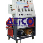
Inside a laboratory for automation technologies, the trainer is the necessary tool for the training of technicians operating industry, for installations maintenance and program designing levels. Totally carried out with industrial components, the trainer enables the development of a solid experimentation and a high content of knowledge on PLC programming and the solution of more complex problems related to automation, with particular reference to process control with HMI/SCADA software and to communication in industrial networks. The PLC installed in the trainer is one of the most powerful and used in industry. It provides many digital inputs and outputs accessible by means of terminals Ø = 4 mm and Ø = 2 mm present on the front panel. The digital outputs are available as relay outputs or transistor outputs for all those applications which need quicker timing. The logic state of the digital inputs and outputs is displayed via LED diodes on the PLC. The analog signals processing allows it to be used within the industrial regulations in closed-loop PID controls.
TRAINING PROGRAM:
The trainer enables the theoretical analysis and the experiments on the following main exercises:
• PLC architecture
• Instructions processing: the cycle concept
• Synchronous, asynchronous and priority cycles
• 8 rotating potentiometers for setting the analog references
• Ø 4 mm and Ø 2 mm standard safety terminals for the connection of I/O to external devices
• Communication Protocol: TCP/IP
• Industrial communication interface: ProfiNet and Profibus
• Performing times, cycle and reaction
• Boolean Algebra
• Combinational logic functions
• Sequential logic functions
• Addressing
• Timers & counters
• Clock generators
• Monostable and bistable circuits
• Algebra operation: addition, subtraction, multiplication, division
• BCD/binary and Binary/BCD conversions
• Integrated functions of fast counting, frequency measurement, positioning
• Program Blocs
• PID control with auto-tuning
• Interrupt related to internal and external events
• Programming and use of industrial operators panels
• Industrial networks: Profinet and Profibus
Typical application
• Mechatronics modules
PID regulations
• Process control (Level, flow, pressure, temperature)
PLC and PC Communication:
• Inputs/Outputs diagnosis
• Internal states diagnosis
• I/O and internal variables forcing
• PLC networks (Master/Slave)
TECHNICAL SPECIFICATIONS:
• Tabletop metal box with press-formed aluminum section structure
• Side handles, not protruding, for easy transport in the laboratory
• Front panel, in insulating material, with silk screen representation of the diagrams and inner components of the
equipment
• 24 Vdc/2 A power supply for control of the digital inputs and outputs. With electronic protection against short-circuits and overloads.
• 24 Vac/2 A power supply relay outputs control with fuse protection against overloads
• 1 31/2-digit digital voltmeter for measurement of the voltage present across the inputs or the analog output 0.1 Vdc resolution.
• 1 Rotating switch for voltmeter input selection
• 8 analog inputs V/I/RTD/TC 16 bit
• 4 analog outputs V/I 16 bit
• Digital inputs: 32 at 24 Vcc, groups of 16
• Digital outputs: 32 at 24 Vcc / 0,5 A
• Digital input simulator with permanent and pulse state switches
• Safety terminals, standard ø 4 mm and ø 2 mm for connection of the inputs and outputs to external devices.
• Digital outputs interfacing
– 16 with 10 Aac/2 Adc relay
– 32 transistor for fast applications
PLC characteristics
• Power Supply: 24 Vdc
• Onboard CPU display (Screen diagonal: 6.1 cm)
• Level 4 protection system
• Hardware clock: YES
• Load memory: 1 MB code
• Data record: 5 MB
• Speed: 10ns Bit operation
• Integrated technology: motion, setting, counting and measuring
• Integrated tracing
• Digital inputs: 32 at 24 Vdc, groups of 16 inputs; Input delay 0,05..20ms; input-type 3; diagnostic interrupt; process interrupt
• Input state display: green LED
• Digital outputs: 32 at 24 Vcc / 0,5 A, groups of 8 outputs, each group 4 A, diagnostic interrupt
• Output state display: LED diodes
• 8 analog inputs V/I/RTD/TC, 16 bit, groups of 8 inputs, Common-mode voltage 10V, diagnostic interrupt
• 4 analog outputs V/I, 16 bit, groups of 4 outputs, diagnostic interrupt
• Ethernet cable for connection to PC included
• Single-phase power supply cable


