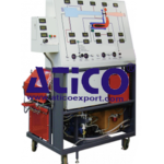
Inside a laboratory for automation technologies, the trainer is the necessary tool for developing solutions and control simple automation processes. Built using industrial components, the trainer enables the development of solutions
to control machines or simple installations, and can be used in the field of Building Automation or in others. The logic module installed in the trainer is one of the most powerful and widespread in both industrial and civil field. It
provides many digital inputs and outputs accessible by means of terminals of Ø 4 mm and Ø 2 mm present on the front panel of the trainer. The digital outputs are available as transistor outputs. The digital inputs and outputs logic state is displayed on the PLC screen. The analog signals processing allows it to be used within the industrial regulations in closed-loop PI controls.
TRAINING PROGRAM:
The trainer enables the theoretical analysis and the experiments on the following main exercises:
• Instructions processing: the cycle concept
• Communications protocol: TCP/IP
• Boolean Algebra
• LAD and FBD basic programming
• Sequential logic functions
• Addressing
• Timers & counters
• Clock generators
• Monostable and bistable circuits
• Mathematical operations
• PI control
• PWM
• Typical applications:
– Simple automation processes
– Building Automation
• PI regulations:
– Process control
TECHNICAL SPECIFICATIONS:
• Tabletop metal box with press-formed aluminium section structure
• Side handles, not protruding, for easy transport in the laboratory
• Front panel in insulating material, with silk screen representation of the diagrams and inner components of the
equipment
• 24 Vdc/1,3A power supply for control of the digital inputs and outputs. With electronic protection against short-circuits and overloads
• 12 digital standard inputs of which 2 configurable as analog
• Digital inputs simulator with permanent and pulse state switches
• 8 24 Vdc digital outputs
• Safety terminals, standard ø 4 mm and ø 2 mm for connection of the inputs and outputs to external devices.
Logic Module features:
• Power Supply: 24 Vdc
• Ethernet interface and integrated WEBServer
• Data logging on internal memory
• Networking of up to 8 basic units over Ethernet
• Program size up to 400 function blocks in all units
• 64 analog merkers
• 64 digital merkers
• 4 Shift registers with 8 Bit each
• Extensive Diagnostics functions
• Configurable startup time (1 … 10 sec.)
• Integrated display (6 x 16 characters, 3 background colors)
• Trace representation for analog signals
• Ethernet cable for connection to PC included
• Single-phase power supply cable
Power supply: 230 Vac 50 Hz single-phase (Other voltage and frequency on request)


