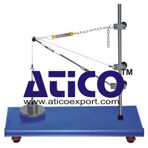
Forces in a Crane Jib
Technical Description :
Based on the example of a crane jib, forces are determined graphically and experimentally: resultant cable force, tensile force, compressive force. The directions and magnitudes of the forces are determined graphically by way of a force parallelogram. A bar of adjustable length and a chain make up the crane jib, which is attached by adjustable clamp elements to a retaining bar. A variety of jib forms can be created. Loads are applied to the crane jib. The occurring bar forces are indicated by integrated spring balances.
Specification:
1. Tensile and compressive forces in a planar central force system based on the example of a crane jib
2. Various jib forms possible
3. Integrated spring balances in the bars
4. Max. load on crane jib 50N
5. Loading with weights set, up to 50N
6. Steel weights, surfaces galvanised
7. Stainless steel retaining bar
8. Sturdy metal frame
9. Handles to aid transportation
10. Box to house the components
Technical Data:
Spring balance for tensile forces
– tensile force: 0…50N, graduations 0,5N
Spring balance for compressive forces
– pressure force: 0…50N, graduations 1N
Weight set
– 1x 1N (hanger)
– 4x 1N
– 1x 5N
– 4x 10N


