Deformation of Trusses
Technical Description:
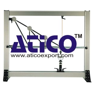
When a component is placed under load it undergoes elastic deformation. This deformation can be calculated by determining elastic lines for example. Elastic lines describe the deformation of the complete component in the form of a mathematical equation. In reality, it is often only the deformation at specific points on the component which is of interest. Energy methods can be applied to determine these deformations more simply. Castigliano’s first theorem uses energy methods to calculate the deformation of a point on the component. The theorem is applicable to both statically determinate and indeterminate systems. This deformation of a single plane truss at one point is determined using Castigliano’s first theorem. The truss under investigation is made of bars joined together by a articulated construction using node discs. The trusses can be considered as ideal trusses. The bars have special snap-lock fixtures on their ends allowing them to be fixed easily into the node discs. A load application device attached to a node disc generates an external force. The range of different bar lengths provided permits three forms of truss to be constructed. The bars are made of PVC, so their deformations are clearly visible. The various elements of the experiment are clearly laid-out and housed securely in a storage system. The complete experimental set-up is arranged in the frame .The well-structured instructional material sets out the fundamentals and provides a step-by-step guide through the experiments.
Specification:
1. Investigation of the deformation of statically determinate trusses
2. Construction of different truss forms possible
3. 2 supports with node discs
4. Load application device with force measurement dial gauge mountable on different node discs
5. Dial gauge to record the deformation of the truss under load
6. Cross arm for lateral stability of truss
7. Storage system to house the components
8. Experimental set-up in frame.
Technical Data:
Truss with 19 PVC bars:
– height of truss max. 450mm
– length of truss max. 900mm
– bar lengths
2x 150mm
5x 259mm
7x 300mm
1x 397mm
3x 424mm
1x 520mm
– angle between bars: 30°, 45°, 60°, 90°
– maximum bar force: 200N
Load application device:
– measuring range: -500…+500N, graduations: 10N
Dial gauge:
– measuring range: 0…0,10mm, graduations: 0,01mm

