Description :
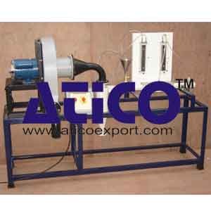
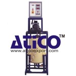
A Cyclone Separator is a vertical cylinder with the inlet stream introduced tangentially near the top, giving the suspension a spinning rotation in the cylinder. The centrifugal force acting on the particles tends to throw them radially to the sides of the cylinder as they spiral downward to a conical bottom where they are removed. A collector is fitted at the bottom & the induced draft blower is used to create the air stream. The classified air leaves the cyclone through a pipe extended down into the cyclone & passes through blower delivery side fitted with fine screen cloth bag to avoid dust expansion in the laboratory.
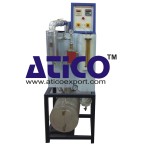
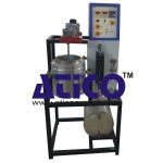
The setup consists of I.D. blower connected to discharge side of Cyclone Separator. A flow meter with manometer is provided to measure the flow rate of air. Pressure drop in the Cyclone is measured by water manometer. Solids are collected in the collector fixed at the bottom. The set-up is complete with flow
Experimentation:
- To study the performance of a given Cyclone.
- To study the effect of inlet gas velocity on overall efficiency
Utilities Required :
- Material for Feed.
- Electric Supply : Single phase, 220 V AC, 1 kW.
- Floor Area 2 m x 1 m.
- Weighing Balance.
Technical Details :
| Cyclone Separator | : Material Stainless Steel, Dia 100mm |
| Solid Discharge Silo. | : Material Stainless Steel, suitable capacity with discharge control valve. |
| Blower | : ID Fan Blower with 1 HP provided motor |
| Air flow measurement | : Flow meter with manometer. |
| Solids Collector | : Transparent PVC container fixed with Cyclone. |
| Fine Dust Collector | : Bag of Nylon cloth fixed on exit of air. |
| Control panel Comprises of: | |
| Standard make On/Off switch, Mains Indicator etc. | |
| Instruction Manual | : An ENGLISH instruction manual will be provided along with the Apparatus |
| A good quality painted rigid MS Structure is provided to support all the parts. | |

