Description
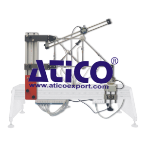
The experiment hardware fits onto a Structures Test Frame. Two supports hold the top and base of one side of a structure. The top support allows pivoting, the base support allows pivoting and rolling. Initially, one of the members is missing from the structure, making it determinate. To make the structure indeterminate, students refi t the missing member. Students manually apply a load to one end of the determinate framework using a screw-thread and electronic load cell. The load cell connects to a Digital Force Display which shows the applied load. Each member of the structure has strain gauges attached. These each connect to a digital strain bridge which shows the member strains. Students use the strains to help them calculate the forces in the structure. A digital deflection indicator measures displacement in the structure. Students note applied load, strains and deflection in a determinate framework. They then repeat the experiment with the frame made indeterminate, and analyze and compare their results. The lecturer guide provides details of the equipment including sample experiment results. The student guide describes how to use the equipment and gives experiment procedures. For extra ‘virtual’ experiments, we can supply the optional Structures Software (STRS), for use on a suitable computer. The virtual experiments simulate the tests you can perform with the hardware. They also extend the choice of tests beyond that available using only the hardware, for example: higher loads, uniform loads or different test specimens. This extends the student’s learning experience. For automatic data acquisition of your experiment results, we can supply the optional Automatic Data Acquisition Unit. Supplied as standard with the Structures Software that displays and logs your experiment results and gives the extra virtual experiments.
Learning outcomes
Study of strains, stresses, forces and deflections in a:
• statically determinate structure; and
• statically indeterminate structure
Specifications
ATICO is committed to a programme of continuous improvement; hence we reserve the right to alter the design and product specifcation without prior notice.
Nett dimensions and weight:
680 x 450 x 100 mm and 6.5 kg
Packed dimensions and weight:
Approximately 0.12 m3 and 8.5 kg
Load application :
500 N electronic load cell
Strain measurement
16-way digital strain bridge
Deflection measurement:
Digital defl ection indicator
Acessories:
Cable to connect to a digital force display
Operating Conditions
Operating environment:
Laboratory
Storage temperature range:
–25°C to +55°C (when packed for transport)
Operating temperature range:
+5°C to +40°C
Operating relative humidity range:
80% at temperatures < 31°C decreasing linearly to 50% at 40°C

