Description
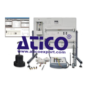
The compact Strain Gauge Trainer fits on a bench or desktop. It contains everything needed to show students how resistance strain gauges work on three different structures. It is ideal for groups of two or more students to do experiments and for classroom demonstrations. Students use the small set of masses to load the bending and torsion systems, and the large set of masses to load the tension system. They use theory and known dimensions to calculate the stresses and strains and compare them with the strains measured by the strain gauges. Students can also connect and compare the performance of quarter, half and full-bridge strain gauge connections for each structure. The bending system uses gauges to measure direct tensile and compression strain. The torsion system shows the use of shear/torque strain gauges. The tension system shows the use of two gauges at right angles in a ‘Tee’ rosette. For more tests with the tension system, we can supply optional tension test specimens made of diff erent metals. Students then use their experience from other experiments to calculate and test strains in the diff erent metals and fi nd their values of Young’s modulus. The tension system also fi nds and proves Poisson’s ratio for tensile and compressive strains in metals. The strain display includes a set of high-accuracy dummy strain gauge resistors (plugs) and controls. These allow the student to connect the strain gauges on the structures as quarter, half or full-bridge networks. The strain display works with and gives correct readings for all bridge connections and diff erent gauge factors. An extra setting on the strain display works with the tension system to prove Poisson’s ratio. The strain display has a socket for connection to optional Versatile Data Acquisition System
Learning Outcomes
Introduction to the equipment and the different bridge connections (quarter, half and full-bridge)
Strains and stresses in a bending system
Strains and stresses in a torsion system
Strains and stresses in a tension system, Poisson’s ratio and Young’s modulus
Tensile strains and stresses in different materials (needs optional tensile specimens) and comparison of Poisson’s ratio and Young’s modulus
Comparison of different strain measurement systems and how they could measure force
Specifications
Sets of masses:
The large mass set gives weights from 0.5 kg to 10 kg in a range of units. The small mass set gives weights from 10 g
to 500 g in 10 g units.
Dummy resistors:
Set of three plugs fitted with high accuracy resistors that match the strain gauges
Strain display:
Multiline display that shows:
• Bridge output voltage (micro-volt)
• Strain reading in micro-strain (me)
• Active arms (gauges)
• Gauge factor
Strain systems:
• Bending system: Four standard gauges fi tted to a given datum on a steel beam, fi xed as a cantilever. Nominal beam cross-section is 5 mm x 20 mm.
• Torsion system: Two sets of identical 45-degree shear/ torque strain gauge rosettes fi tted to a torsion bar. Nominal bar diameter is 10 mm.
• Tension system: Two sets of identical 90-degree ‘Tee’ strain gauge rosettes fi tted to a tensile test specimen. Steel specimen supplied as standard. Nominal tension specimen cross-section is 2 mm x 10 mm.
Operating Conditions
Operating environment:
Laboratory
Storage temperature range:
–25°C to +55°C (when packed for transport)
Operating temperature range:
+5°C to +40°C
Operating relative humidity range:
80% at temperatures < 31°C decreasing linearly to 50% at 40°C

