Description
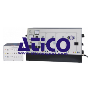
This equipment works with a suitable three-phase supply and load to show how the most common circuit protection devices perform. It allows students to adjust the fault current in four different protection circuits to test and compare them. A variable transformer inside the unit works with the load to set and control the fault current in each of four circuits. Each circuit has a different current protection device, including fuses, a magnetic only circuit-breaker, a thermal only circuit-breaker, and a thermomagnetic circuit breaker. To show students how industrial switching circuits work, each circuit includes a contact breaker, switched by an industrial standard discrepancy switch. Circuit one includes an additional adjustable residual current detector for experiments with different residual current faults. It includes a digital display and switches to help set the earth leakage fault current before the test. Circuit two tests fuses and includes a ‘fuse break’ detector circuit. This uses lamps to show the students when each of the fuses breaks (one fuse for each of the three phases). It shows the fault current and breaking time relationship for different fuse types. Circuit three also includes remote and local control key switches to switch its contact breaker and break the circuit. This helps to show how both a control room operator or a remote operator can switch a circuit on or off in a real installation. Each circuit finishes at colour-coded shrouded sockets for safe and easy connection to the resistive load(supplied). The equipment includes meters that measure the incoming voltage and current to the test circuits.
Learning Outcomes
- Circuit overcurrent protection – using four different types of circuit protection
- Protection device rating and circuit current
- Local and remote control (of circuit breaking)
- Residual current detection (earth leakage) – with balanced and unbalanced loads
Features
- Compares four of the most common protection devices, including fuses and thermal and magnetic circuit-breakers
- Includes a ‘fuse break’ detector – for safe tests
- Includes industry-standard discrepancy switch circuits – to show how industrial switching works
- Shows residual current protection in three-phase circuits and shows how it works with balanced
and unbalanced loads - Includes keyswitches – to show local and remote circuit breaker control used in industry
- Includes a resistive Load Bank
Specifications
ATICO is committed to a programme of continuous improvement; hence we reserve the right to alter the design and product specification without prior notice.
Dimensions and weight:
Nett: 1000 mm wide x 500 mm high x 420 mm front to back and 102 kg
Approximate packed: 0.34 m3 and 150 kg
Load bank:
Refer to separate datasheet .
Circuit 1:
Thermomagnetic Miniature Circuit Breaker (MCB) with C curve characteristics and an Adjustable Residual Current Detector (RCD).
Circuit 2:
Three type gG cartridge fuses in carriers. Includes a ‘fuse break’ detector circuit.
Circuit 3:
Thermal overload and remote/local key switches.
Circuit 4:
Magnetic circuit breaker with F2 curve characteristics
Operating Conditions
- Operating Environment:
Laboratory - Storage Temprature Range :
–25°C to +55°C (when packed for transport) - Operating Temprature range:
+5°C to +40°C - Operating relative humidity range:
80% at temperatures < 31°C decreasing linearly to 50% at 40°C

