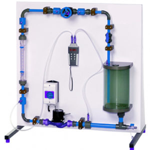
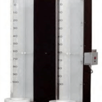
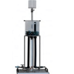
Hydraulic circuits are designed according to their task and their area of application. Designing hydraulic circuits requires knowledge of flow behaviour and pressure losses in valves and fittings, as well as characteristics of the pump. A hydraulic circuit can be compared to an electrical circuit. This analogy can be made evident in the experimental unit.
The experimental unit includes a centrifugal pump, a rotameter, a diaphragm valve, a water tank and various other valves and fittings. After filling the system once the experimental unit can be operated independently from the water supply.
Learning Objectives And Experiments
- Recording the pump characteristic
- Pressure losses at various valves and fittings depending on the flow
- Determination of the operating point in a hydrostatic circuit
Features
- Measurement of pressure conditions in valves and fittings and a pump
- Measurement of the flow rate
- Clearly arranged pump circuit
Specification
- Pressure conditions at various measuring objects
- Measuring objects: pump, flow meter, diaphragm valve
- Centrifugal pump with 3 different speeds
- Closed water circuit
- Flow can be adjusted via valves
- Flow measurement using rotameter
- Annular chambers allow easy measurement of pressure
Differential pressure measurement using electronic pressure meter
Technical Specification
- Tank: Volume: 8,5L
- Pump: Max. Power consumption: 70W
- Max. Flow rate: 5m3/h
- Max. Head: 6m
- Three switching stages for speed selection
Measuring ranges
- Flow rate: 150…1600L/h
- Differential pressure: ±350mbar
- 230V, 50Hz, 1 phase
- 230V, 60Hz, 1 phase; 120V, 60Hz, 1 phase

