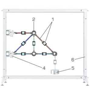
Trusses are bar structures in which the bars are only subject to compressive or tensile stress, but not bending.Contains various smart, communication-enabled bars, equipped with electronic modules for data acquisition and measured value display. The experimental arrangement is set up in the mounting frame. The stainless steel mounting frame provides direct and wireless data transmission and power supply for the smart components.
The bars are hinge-connected to node disks and are only subjected to compression or tension. The click system ensures the bars easily snap into place in the node disks. Since no torques are transmitted in the node disks, they are considered frictionless. The trusses can therefore be regarded as ideal trusses.
Accessories such as supports, vertical load, load unit and additional bars are available for setup and for free experimentation. It is possible to create bridge connections, trusses across corners, larger trusses and indeterminate trusses. In experiments, all forces of the plane truss (bars, supports, loads) are measured and displayed both directly on the smart components and in the software as a measured value and as a colour. The calculated displacement can be demonstrated and amplified in the software. With the distance measurement accessory, the displacement can be measured and compared at any points.
Specification
bar and support forces in various plane trusses
smart, communication-enabled bars with electronic modules for data acquisition and display of measured values
node disks hinge-connected to bars
setup experiment in the mounting frame
click system for simple, quick experimental setup without cabling
supports, vertical load, load unit, distance measurement, additional bars available as accessories
setup variants across corners and with bridge connection, as well as free experimentation possible
bar extension for setting up indeterminate trusses
automatic identification and assignment of the bars during setup and experimentation
Algorithm: visualisation in the software corresponds to the real assembled truss
display of measured values and visual representation of forces by colour directly on the bars and in the software
calculated displacement can be demonstrated and amplified in the software
distance measurement for measuring displacement at any points available as accessory
software via USB under Windows 10 digital multimedia teaching material online in the SCIENCE Media Center: E‑Learning course, worksheets
Technical data
Bars with electronic modules
1x bar extension, adjustable length
2x 424mm
4x 300mm
1x 259mm
per bar: 2x LED for coloured display of force
per bar: display for measured force and angular position
Node disks
quantity: 3
outer connection positions: 16
inner connection positions: 1
Measuring ranges
force: 0…200N
angle: 0…180°

