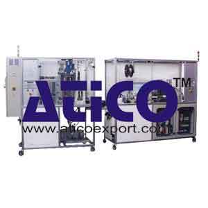
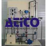
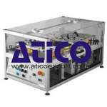
Automated Candle Manufacturing Line Training System
Automated Candle Manufacturing Line Training System: This automated system represents a candles manufacturing line of type” dish warmer” made of paraffin and decompose itself in two parts.
A first part allows to manufacture the paraffin pastilles with or without colour and a second, part can offer the possibility to crimp and to cut the wick to the desired length and to assemble the whole in a capsule and to package the finished product in boxes. The finished product is perfectly usable.
Recyclable product:
The finished product is recyclable with the help of the crusher, which limits the supply of raw materials.
Module 1:
1 Operative part:
- Transformation of the paraffin in granules or in pastilles in the case of the recycling in powder.
- Manual filling of the paraffin in powder in the hopper constituted of a endless screw allowing to fill the mixer.
- Dosing of one or all powdered colorants with alveolar dispensers.
- Mixture of the paraffin and colorant(s) with the help of a mixer.
- Dosing of the mixture with the help of an alveolar dispenser.
- Handling of the dose with the help of a pneumatic jack over of the mold.
- Compression with a hydraulic jack.
- Ejection with an air jack.
- Evacuation on a conveyor of the manufactured pastille (with the drilling allowing to receive the wick for the 2nd part).
2 Pre-actuators:
- Contactors,
- 3 bistable distributors 5/2.
- 2 monostable distributors 5/2.
- 1 hydraulics distributor 4/3.
- 1 venturi.
3 Actuators:
- 1 crusher (independent of the chain) of 1,5Kw.
- 3 direct current gear motor of 15W for the alveolar dispensers.
- 1 gear motor of 0,29 kW for the endless screw hopper.
- 1 gear motor of 0,25 kW for the mixer.
- 2 simple acting and double acting pneumatics jacks.
- 1 hydraulic unit of 2,2 kW.
- 1 gear motor of 90 W for the conveyor.
- 2 pulverization nozzles of stripping agent.
4 Sensors:
- 4 inductive detectors,
- 2 high pressure inductive detectors,
- 3 capacitive detectors for powdery,
- 5 ILS detectors on jacks,
- 1 force detector, electronic interface with analogical output,
- 1 stealth detector with security logical block,
- 1 electronic pressure switch with display and output
Module 2:
1 Operative part:
- Control of the height of the pastille with a fiber optics.
- Feeding of the pastilles with a conveyor and an indexing table to the different stations.
- Feeding of the cups with a vibratory feed bowl.
- Separation of the cups with an pneumatic jack.
- Arrangement of cups at the crimping station with a pneumatic jack.
- Feeding of the wick with pneumatic grip.
- Crimping of the cup with the wick and cutting of the wick with the help of 2 pneumatic jacks.
- Supplying and placing the capsule on the pastille with the help of 2 pneumatic jacks.
- Evacuation of the candles at the end of the rotary table with an pneumatic rotary jack.
- Formation of candles rows with the help of an air jack without rod.
- Emptying out of the empty boxes (bottom of the box) with the help of a pneumatic jack without rod.
- Plating and Reversing of the box with the help of a compact jack and a pneumatic rotary jack.
- Deposing the lid and evacuation of the box with the help of a pneumatic jack without rod.
2 Pre-actuators:
- 1 vibratory feed bowl and speed driver.
- 1 indexing table with orthogonal shafts.
- 3 simple acting pneumatic jacks0
- 1 simple acting pneumatic grip.
- 5 compact double acting pneumatic jacks.
- 2 rotary pneumatic jacks with pallet.
- 3 pneumatic jacks without guided rod.
3 Actuators:
- Contactors.
- 10 bistable distributors 5/2.
- 6 monostable distributors 5/2.
4 Sensors
- 4 optic fibers with amplifiers for feeding of the pastilles, cups, capsules.
- 1 electric photo detector for the feeding of the pastilles.
- 01 inductive detector for the presence of the capsules.
- 25 ILS and electronic detectors on the jacks.
- 3 micro cells for the feeding of the boxes.
5. Operating part :
PLC with analogical ON-OFF inputs/outputs, and ON-OFF remote inputs/outputs.
- A MAGELIS interactive console display, communication with PLC over serial line, UNI-TELWAY protocol, allowing the input of system parameters,
- 1 control cabinet on module 1,
- 2 control cabinets on module 2,
- A PC supervisor with Modbus/Jbus protocol, connected to the PLC via an RS232-RS485 converter and a PCMCIA network card on the PLC.
6. Supervision:
The supervision allows the display of state, of the system defaults. It also serves to the supervision and monitoring with several screen displays for the user with in particular the sequential function charts in real time.
7. Presentation:
- Entirely protected with a safety guard with opening on the front side.
Dimensions :
- Module 1: L x l x h = 800 x 1950 x 2000mm.
- Module 2: L x l x h = 800 x 2200 x 2000mm.
8. Educational features:
The cycle is described via sequential function charts and the Gemma (Studying guide of the on/off modes). The different actions are described as tasks, regrouped in a tasks sequential function charts at the level of the program structure.
9. Educational applications:
- Industrial Maintenance, Functional analysis of the system, Automatism, Dialogue between console display – PLC and supervision – PLC, – Industrial Mechanics.
9.1 Conduct of automated system:
- Exploitation of production line: – with the help of the interface man / machine, – And of the supervision,
- These 2 components allow to register the parameters necessary to the working of the automated system ; numbers of manufactured candles, the defaults, lack of raw materials, as well as to inform the user on the state of the chain at any times.
9.2 Industrial mechanics:
- – Study of the technological choices chosen for the operative part according to some characteristics (speed, course, storage capacity, cycle time.
9.3 Automatism:
- – Dialogue man/machine with the dialog MAGELIS control display and the supervision.
- – Visualization of the defaults, and of the state of the machine at any time (synoptic of the different parts,sequential function charts, real time GEMMA ).
- – Visualization of the state of the sensors and motors.
Study of the on/off modes:
Possibility to run the machine following 2 modes:
- Normal working mode (F1).
- Random step-by-step mode (F4).
Study of the architecture network:
- Information exchange between the control display, the PLC, the supervisor.
Functional analysis of the system :
- Identification and segmentation of the automated system in tasks.
- Research of the antecedences between the tasks.
- Development of the sequential function charts.
Study of the rates with the coordination of the tasks for the normal working:
- Optimisation of the rates.
- Comparison between the real behaviour of the system and the temporal simulation of the working cycle.
9.4 Industrial Maintenance:
Research of faults:
- The remote inputs/outputs used offer the possibility to easily simulate the faults.
- The connectors at each sensor allows their replacement by a deficient sensor.
- Help to the diagnosis with the help of the control display and the supervisor.
- Mechanical elements maintenance after a given working time (as indicated in the constructors leaflets):
For the colorant dispensers, the mixer and the hopper after a given working time:
- Cleaning of the hoppers.
- Cleaning of the endless screw.
- Cleaning of the mixer.
For the mold after a given working time:
- Cleaning of the inner sides and the piston
For the hydraulic unit:
- Checking of the oil level.
- Setting of the pressure.
- Setting of the speed limiter.
For the conveyor belt:
- Setting of the tension of the belt.
- Centring of the belt in accordance with the structure of the belt.
For the translation module of the mixture dose:
- Checking and setting of the compression spring.
For the strength sensor under the dosing hopper:
- Calibration of the sensor.
For the whole of the electrical mechanical and pneumatic equipments:
- Checking or replacement of the parts according to the constructor’s recommendations, listed in the educational file.
For the feeding in wick after a given working time:
- Cleaning of the pieces allowing to guide the wick with paraffin.
For the guidance edges under and at the output of the indexer:
- Cleaning of the pieces to remove the residues of paraffin.
For the pneumatic jacks:
- Verification of the position of the sensors (ILS).

